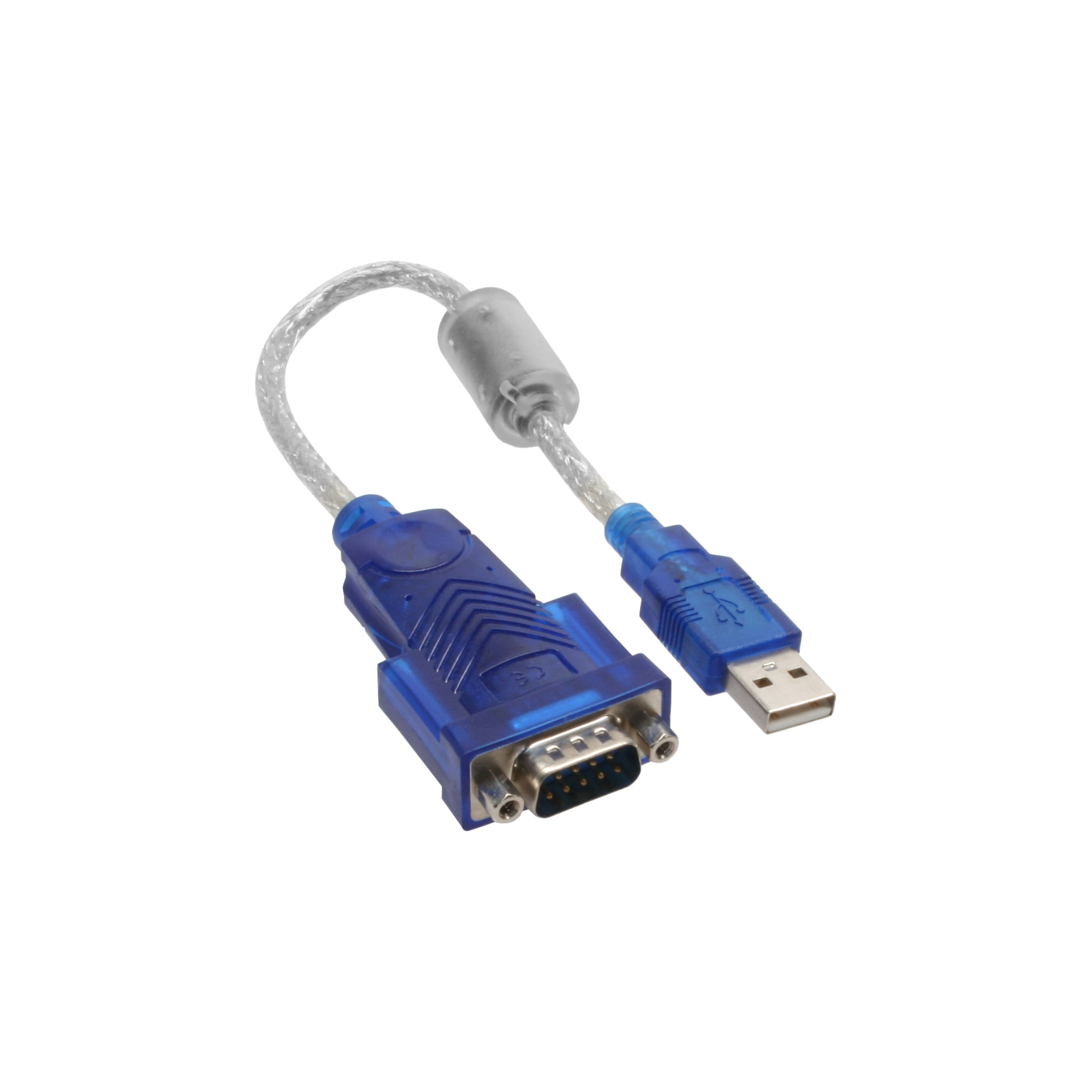

Some chips have Windows drivers built-in to Windows or distributed through Windows Update, creating a plug-and-play experience. The CP2102 and PL2302HXD only output a maximum 3.3V, but can take up to 5V as input, making them compatible with 5V UART devices.īesides the differences in the chips, the quality of the drivers also differs between the various chips.These have different versions with different specs: Chip There are several commonly used chip families: The computer sends data to this serial port and the module converts it to UART signals.Ī USB to UART bridge has a chip on it specifically for this purpose. It pretends to be a serial port to your computer. This is a small device that plugs into your USB port and has at least ground, Rx and Tx outputs. To let your computer talk UART, you need a device that converts computer bytes to UART signals a USB to UART converter module. So in that case it is possible to communicate with a 5V UART using a 3.3V UART. 5V TTL voltage levels consider everything above 2V a logic high, and can thus also receive data from 3.3V UART devices. Voltage that ranges between 0 and power supply voltage (Vcc) is also called TTL voltage levels. Connecting your 3.3V bridge to a 15V RS232 line will quickly destroy it. To avoid frying your device, it is important to use the correct voltage. For most other UART devices, 0V indicates a 0 bit and the higher voltage indicates a 1 bit. Some devices use 0V and 5V, such as an Arduino Uno that runs on 5V.įor RS232, negative voltage is a logical 1, positive voltage a 0.RS232 serial ports use negative and positive voltages, up to -15V and 15V.What voltage exactly is used depends on the device: UARTs use two voltages: one voltage indicates a 0 bit and another voltage indicates a 1 bit. So the transmitting party first sends a start bit, then eight data bits, followed by a stop bit. By far the most common configuration is to use eight data bits, no parity bit and one stop bit, or 8N1. UART frames consist of a start bit, seven or eight data bits, optionally a parity bit and one or two stop bits. It is possible to use different baud rates for sending and receiving, although this is pretty rare. In theory you can use any baud rate, but old interfaces only support the standard baud rates. Then there are a handful of standard baud rates, such as 1920. The most common baud rates in use are 9600. This sometimes happens with microcontrollers, that have trouble keeping an exact clock. It will still work if this is off by a couple of per cent. The sending party flips the signal every 104µs, and the receiving party checks the voltage on the line every 104µs. In that case, one bit takes up 1∕ 9600 of a second, or 104µs. A common baud rate is 9600 bits per second. The baud rate is a term for the number of bits per second that are transmitted over the wire. To correctly communicate, both devices must be configured beforehand to use the same speed of communication, called the baud rate. There is no clock signal and no negotiation between the two devices. UART uses a binary protocol, so there are only two voltage levels: high and low. Now, the devices can send data to each other by varying the voltage on the Tx lines, and read data by checking the voltage on the Rx line. For isolated adapters, Vcc or the positive lead of the power supply.The transmitting pin (Tx) of one device is connected to the receiving pin (Rx) of the other device.Common ground, or 0V, or the negative lead of the power supply.When two devices communicate using UART, they are connected with at least three wires: These can be used with USB to UART bridges, but require further hacking to get working. Several other protocols are built upon UART communication, such as IrDA, DMX, MIDI and smart meter P1 ports. UART communication is sometimes also needed to interact with a development board, such as an Arduino or ESP8266, although most of these boards have a USB to serial converter on board. Often, this gives direct access to a root shell. The device sends console output and accepts commands over the UART interface. Most embedded devices have a UART header on the board. Applicationsįrom a hacking perspective, the most interesting application of UARTs is in embedded devices. In this post we’ll look into how this works. They can be used to make a serial connection to another device. USB to UART converters or bridges present themselves as a serial port to your computer and send serial data over a couple of wires.


 0 kommentar(er)
